Run your PDP-11 application today in a DOS/Windows environment on a PC with Strobe Data's Osprey Co-Processor add-in card. No conversion. No software re-write. Lower maintenance costs, greater throughput, PC networking, and PC software packages (spreadsheets, stat packs, word processing, e-mail, etc.) are yours to enjoy IMMEDIATELY.
Your valuable software, still running on a PDP-11 you installed many years ago, is mature, bug-free and very productive. But how much upgrade money have you already spent to keep that application alive? And how long can you keep it running on replacement parts from the used computer market?
You know the time is coming to say goodbye to your PDP-11. But you also know that porting old applications to new computer architectures is tricky, expensive, and high risk!
Osprey/PC to the rescue!
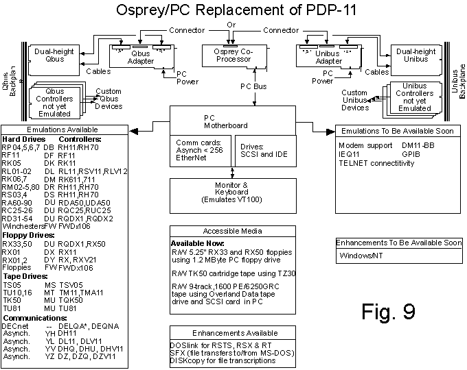
This is all it takes to execute your PDP-11 application on a PC with Osprey Co-Processor. An Osprey/PC is a modern PC with Osprey Co-Processor ISA/EISA add-in card or card set. The Osprey contains CPU and memory and all other logic needed to execute PDP-11 instructions (CPU and memory). The PC provides the devices which replace the standard PDP-11 peripherals (console,
keyboard, serial lines, printer ports, hard disks, diskette units, tape drives, etc). Real PDP-11 peripherals are treated as "virtual devices" on the Osprey by a mapping process which equates the PDP-11 console keyboard to the PC keyboard, a PDP-11 hard disk to a PC container file, and so forth. PDP-11 controllers and devices which are not emulated in this way (custom controllers, for example) are supplied with actual Q-bus or Unibus* signals corresponding to the PDP-11 backplane signals by means of Osprey bus adapters. The Osprey is available with a 18MHz clock rate. The Basic Osprey is a single PC card for applications in which all the I/O is
virtualized. Unibus and Q-bus signals require an Osprey 2-card set.
Osprey Model Designations

The 15 MHz boards are no longer available


                          15 MHz        18MHz


   no backplane signal    Osprey/15B   Osprey/18B     single card


         Q-bus signals    Osprey/15Q   Osprey/18Q     dual card set


        Unibus signals    Osprey/15U   Osprey/18U     dual card set
EMI and Osprey Rack-Mountable Chassis
If your application uses a device not in the Osprey device emulation list, and "real I/O" in the form of PDP-11 backplane signals is needed, consideration must be given to shielding the cables between the Osprey card set and the PDP-11 custom device where local EMI (Electro-Magnetic Interference) regulations must be met. This requires housing the connecting cables in a cabinet certified by the regulating agency. Strobe Data offers an EMI certifiable rack mountable chassis, RMOC Q or RMOC U, to accommodate the host PC motherboard, disk drives, Osprey card set, and custom PDP-11 devices. Where no EMI regulations exist, it is possible to retain the original PDP-11 cabinet and run the cables externally between a DECpc, for example, and the existing PDP-11 cabinet.
Serial Lines - The StrobeMux
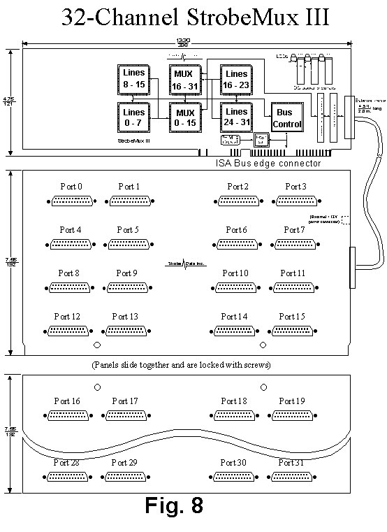
As shown in Figure 8, PDP-11 serial lines can be mapped onto the serial lines (COM1 and COM2) configured with the host PC. For applications requiring more than 2 serial lines, Strobe Data offers a 16 or 32 channel PC-compatible multiplexer, the StrobeMux. Serial line configurations of 128 ports or more can be supported by Osprey/PC systems.
Virtualizing PDP-11 custom devices
Most standard PDP-11 peripherals are already emulated on the Osprey/PC as the list of virtualized devices in Figure 9 shows. However, there exists a wealth of applications which use devices other than the standard hardware found in that list. In many cases, the devices lend themselves to virtualization on the PC. Strobe offers the Osprey Programmer's Development Kit to software developers who wish to eliminate the actual PDP-11 backplane and drive emulated devices directly from the PC.
The following types of devices can be emulated:
OSPREY PRODUCT LIST
This is the basic single Osprey card. All I/O is virtualized to PC devices.
Osprey 18Q
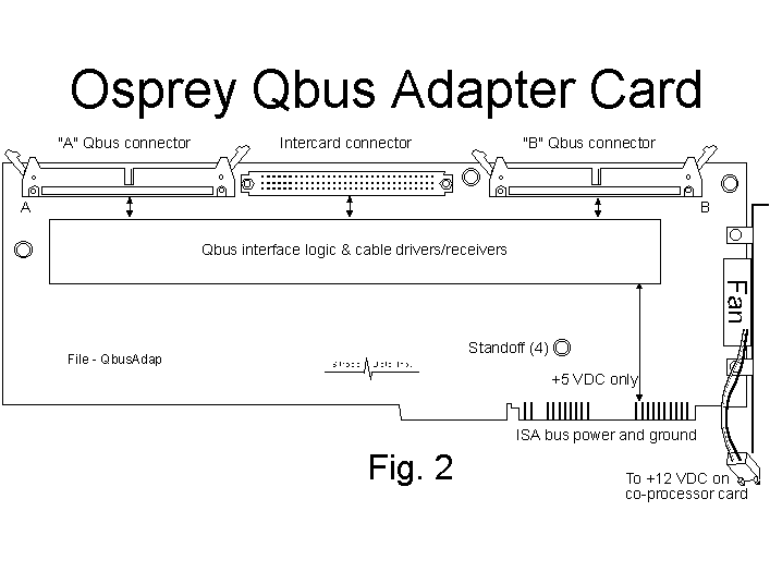
This is a dual-card set, comprising Osprey Co-Processor and Adapter cards for Qbus* signals attached to one another mechanically by screws, and electrically by an intercard signal connector. Its Virtual I/O detector circuitry routes calls for custom devices to the Adapter card shown in Figure 2. The two external connections on the Adapter card provide Q-bus signals via ribbon cables to the Backplane Extender card for Qbus shown in Figure 3.
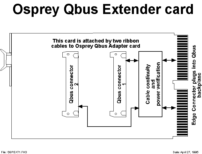
This Backplane Extender Kit for the Qbus, shown in Figure 3, comprises a pair of ribbon cables and a dual-width card compatible with the PDP-11 Qbus backplane. It provides the connection to either the PDP-11 backplane or the RMOC Q backplane to drive custom devices. This card is one of the tools available to the Osprey installer to move files from the PDP-11 to the Osprey/PC.
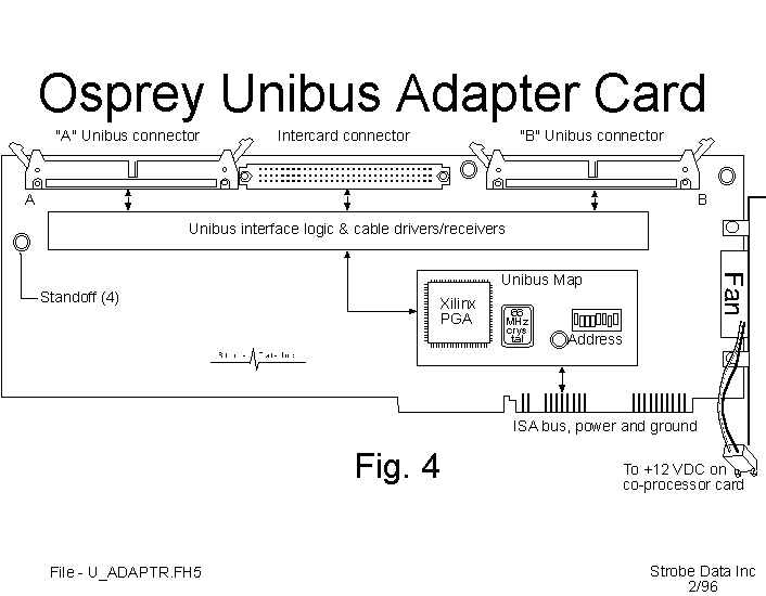
This is a dual-card set, comprising Osprey Co-Processor and Adapter cards for Unibus signals attached to one another mechanically by screws, and electrically by an intercard signal connector. Its Virtual I/O detector circuitry routes calls for custom devices to the Adapter card shown in Figure 4. The two external connections on the Adapter card provide Unibus signals via ribbon cables to the Backplane Extender card for the Unibus.
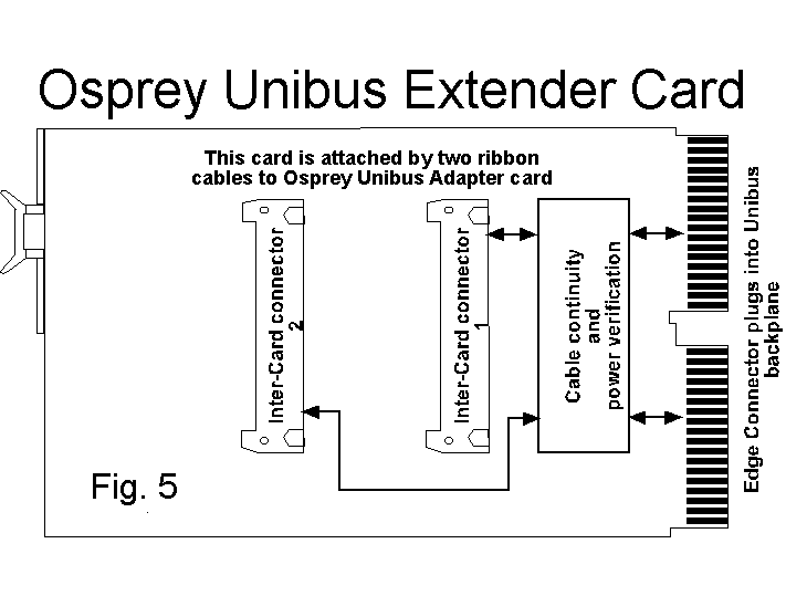
This Backplane Extender Kit for the Unibus, shown in Figure 5, comprises a pair of ribbon cables and a dual-width card compatible with the PDP-11 Unibus backplane. It provides the connection to either the PDP-11 backplane or the RMOC U backplane to drive custom devices. This card is one of the tools available to the Osprey installer to move files from the PDP-11 to the Osprey/PC.
The Q-bus compatible Rack Mountable Osprey Chassis is shown in Figure 6. EMI certifiable, this chassis accommodates a PC motherboard, three visible and one hidden half-height PC drives (hard or floppy disk, cartridge tape, CD-ROM, etc.), and four quad-width Qbus compatible cards. Short ribbon cables route Qbus signals to the rear of the built-in Qbus compatible backplane. The 450 watt power supply has its own internal cooling fan, and is sufficient to power a fully loaded chassis. Two sets of dual-fans add cooling to the PC and Qbus compatible areas.
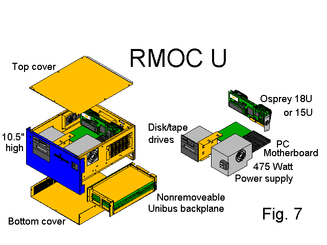
RMOC U
The Unibus compatible Rack Mountable Osprey Chassis is shown in Figure 7. EMI certifiable, this chassis accommodates a PC motherboard, three visible and one hidden half-height PC drives (hard or floppy disk, cartridge tape, CD-ROM, etc.), and the user's four-slot, hex-wide Unibus backplane. Short ribbon cables route Unibus signals to the A-B slot in the user's Unibus backplane. The 450 watt power supply has its own internal cooling fan, and is sufficent to power a fully loaded chassis. The user must specify the current levels and voltages required for the intended custom Unibus compatible cards. Two sets of dual-fans add cooling to the PC and Unibus compatible areas.
Where more than two serial lines are required, the StrobeMux III-16 and III-32 offer 16 and 32 channels, respectively. Several models of the StrobeMux III are supported by the Osprey/PC, including RS232, RS422, and 20 milliamp current loop versions. Each channel is individually specified in the OSPREY.CNF file for mode, speed, and related parameters. User cables are terminated on external panel(s) provided with the StrobeMux III card.
Osprey Programmer's Development Kit
This tool kit, enabling the sophisticated programmer to "virtualize" I/O not already emulated in the Osprey virtual I/O list, requires signing a non-disclosure agreement with Strobe Data Inc. It contains, not only the software tools needed to build the necessary drivers, but samples and documentation of the portions of the Osprey emulation and system communication software necessary to produce virtual device drivers for the system.